Designing and Building the Copper Drive Guitar Pedal
This is a custom overdrive pedal with switchable clipping. The aim was to create a pedal that is somewhere between an overdrive and a fuzz. Something with a nice punchy sound, with options to add some clipping for extra grit.
Designing the Circuit
The circuit has two gain stages, a JFET pre-amp stage and a BJT amplifier stage.
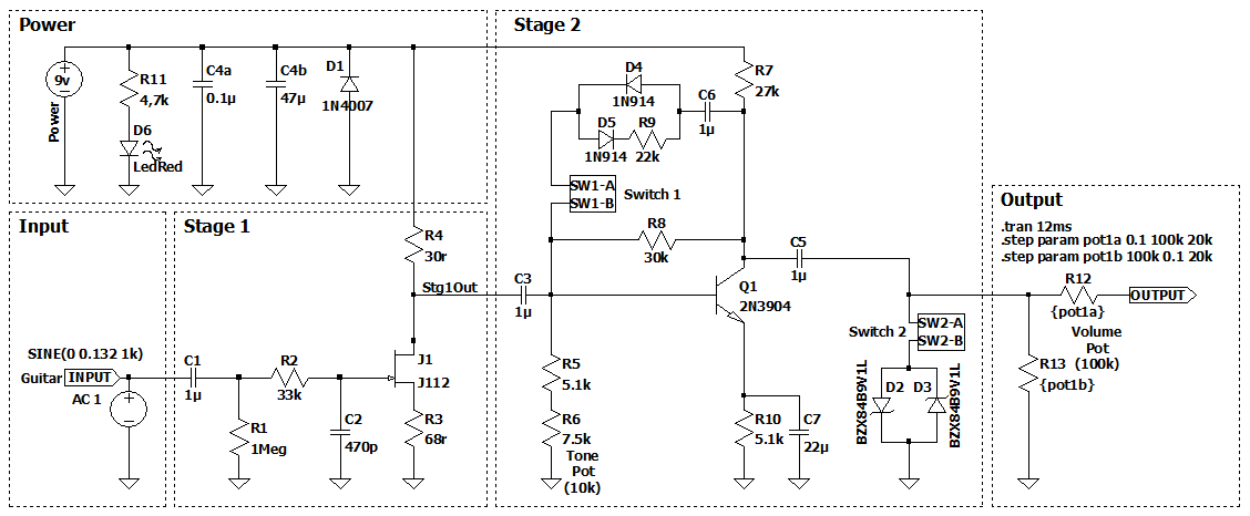
Stage 1 - JFET Pre-Amp
Stage 1 is based on the Fetzer Valve circuit from Run Off Groove. This uses a JFET transistor to emulate the first stage found in a typical Fender tube amp (12AX7). While this shapes the tone, it actually looses gain.
The JFET used here is a J112 transistor. All JFETs are slightly different and must be biased correctly to get the desired effect. The Vp and Idss values for the chosen transistor can be measured using the method described here: Measurement of Vp and Idss. The values for this J112 are 3.8V and 48mA respectively.
The Fetzer Valve calculator was then used to calculate the source and drain resistor values. The calculator gives values of: Rs = 66Ω and Rd = 26Ω. The closest standard resistor values are: Rs = 68Ω and Rd = 30Ω.
Stage 2 - BJT Amplifier
Stage 2 is a Common Emitter amplifier with the popular 2N3904 NPN transistor to amplify the signal.
Tone Control
The tone control is at the start of this stage. It's a basic High Pass Filter comprised of the 1µF coupling capacitor (between stages 1 & 2), a 5.1kΩ resistor and a 10kΩ linear potentiometer to adjust the cutoff frequency. This allows cutting low-end frequencies, ranging from below below 10Hz to below 30Hz.
Clipping
There are two sets of clipping diodes; soft clipping in the feedback loop and hard clipping on the output. Originally I was going to use an On-Off-On switch to toggle between them, however, it sounded good with both on together so I used an On-Off switch on each.
The soft clipping in the feedback loop uses two 1N914 silicon diodes in parallel. There is a 22kΩ resistor in series with one of the diodes to create asymmetric clipping.
The hard clipping at the output uses two BZX55C 9V1 Zener diodes in parallel, shunting to ground.
Output
Finally, there is a 100kΩ potentiometer on the output for a volume control.
Modelling the Circuit
The circuit was modelled in LTspice, with the input signal trace shown here in green and the output signal shown in red.
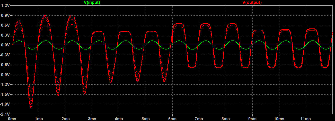
This trace is plotted over 12 milliseconds showing the four combinations of clipping, for 3 milliseconds each; Off-Off, On-Off, Off-On, On-On. These combinations add different levels of clipping to the signal and different colours to the tone.
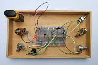
Prototype
The prototype was built on a breadboard to test the circuit and make adjustments.
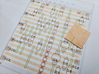
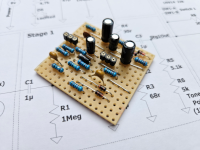
Designing the Circuit Board Layout
VeeCAD was used to design the stripboard layout, using a 15 x 16 hole board, with a few cuts in the strips.
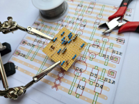
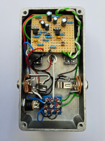
Building the Circuit
Pretty standard circuit build, with sockets for the transistors.
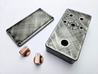
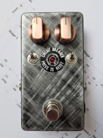
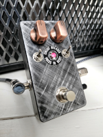
Preparing the Enclosure
I had two copper coloured knobs from a previous project, so I decided to go for a rustic steampunk theme, rather than a plain paint job.
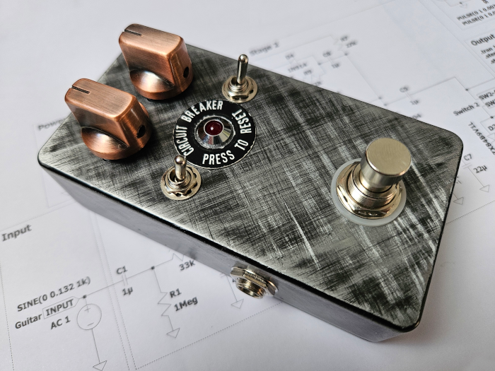
After the enclosure had been drilled for the pots, switches, jacks etc, it was etched with course sandpaper in cross-hatch pattern. This was given a light spray of matt black paint. Once dry is was sanded again with finer sandpaper to remove the paint from the high points, leaving the low points black. Finally, it was given a few coats of clear coat to protect the finish.
The "Circuit Breaker" decal around the LED is something I found in an old box of bits & pieces, not sure where it came from but it looks kinda cool!
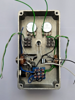
Off Board Wiring & Assembly
Nothing unusual with the off board wiring; jacks, power, LED, and a standard bypass setup on the footswitch. Two toggle switches were added for the clipping diodes. The back of the pots and inside of the enclosure was covered with insulating tape to prevent shorting out on the stripboard.
The End Result
It turned out quite well, and it stacks well with other drive and fuzz pedals.
Demos
A short demo of the Copper Drive, this was recorded through a Headrush Gigboard with a Vox AC 30 amp simulation.
Both clipping switches are toggled on for the rythmn track and toggled off for the lead track: