ArchiMate - Wish List
This article is part of the The ArchiMate Series
I have used ArchiMate for several years with great success but there are times when I wish the specification contained some additional elements, here is my wish list:
Decision Element
Neither the Motivation or Strategy layers have an element to explicitly represent a decision.
The Assessment element alludes to a decision to a degree, from the specification; an assessment represents the result of an analysis of the state of affairs of the enterprise with respect to some driver
. But we often carry out assessments for several alternative options, and then make a decision to proceed with one of them.
The Outcome element represents an end result that has been achieved
, not necessarily what we decided to do so this doesn't really cover it either.
A Course of Action element represents what an enterprise has decided to do
, and can be categorized as strategies and tactics
. The example in the specification shows two Courses of Action influencing two separate Outcomes which influence Goals in either a Positive or Negative way but there is no explicit Decision, it's not making a choice between the options.
The example in Fig 1. shows two Capabilities, joined by an Or junction which is explained using a Meaning element, realising one Course of Action, influencing an Outcome, this almost works but doesn't feel quite right.
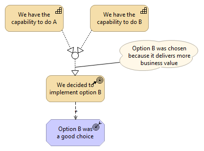
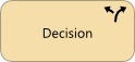
Given the importance of decisions in documenting an architecture I think they deserve to be first class citizens in ArchiMate. Fig 2. shows what a Decision element might look like.
Rationale Element
Similar to the Decision element above, the Motivation layer doesn't have an element to represent the rationale behind decisions which have been made.
According to the specification, the Meaning element can be used to represent the knowledge or expertise present in, or the interpretation given to, a core element in a particular context
, a description that expresses the intent of that element
. I guess this could be used to represent rationale but, similar to decisions, I think that the Rationale behind decisions deserves to be represented as a first class citizen in ArchiMate.
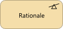
Fig 3. shows what a Rationale element might look like.
Data Storage Element
How many times have you seen a system architecture diagram where a cylinder is used to represent a database or other type of data store? It's easily recognisable and well understood, probably because it looks like a big barrel of data and it just feels right.
Representing a database with a System Software element or a Technology Service element along with an Artifact doesn't convey the same message, it feels awkward. A System Software element could be stereotyped with RDBMS but its not the same, people expect to see a cylindrical element or at least a cylinder shaped icon.
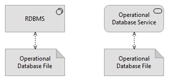
A Data Storage element would be an Active Structure element, it could be used to represent multiples types of data storage; databases, document management systems, code repositories etc. Fig 5. shows what a Data Storage element might look like.

Bi-Directional Flow Relationship
Information quite often flows in both directions so it would be useful if the Flow relationship was bi-directional, just like the Access relationship. I'm not sure how this would be implemented however, the Access relationship is not truly bi-directional, it is always from a behaviour element to a passive element, the access type is where the directionality comes from, the options being; read, write and read-write.
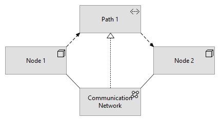
Path Relationship
In the technology layer, we can use tbe Path element to model the logical communication relations between nodes
. We can also use the Flow relationship to represent the direction of the communication. A Path is the logical realisaton of a physical Communications Network.
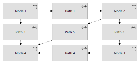
This works fine where there are a small number of nodes in a view but quickly becomes cumbersome as more nodes are added. Fig 7. shows four nodes with the Paths between them.
In Fig 8. the Path elements have been removed. By using direct Flow relationships this view is much easier to read.
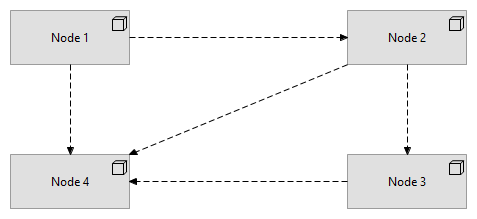
While the Flow relationship does the job it would be more explicit if the Path element was a relationship.