Building a Run Off Groove Supreaux Deux Guitar Pedal Kit
The Supreaux Deux Amp Sim stompbox circuit was designed by Run Off Groove. It's based on the vintage Supro 16T amplifier which is similar to the amp used by Jimmy Page on Led Zeppelin I. This kit was supplied by Musikding and it includes a PCB printed by TH Custom Effects.
The base kit can be purchased without a pedal enclosure and knobs, but you will probably want to add a blank or pre-drilled 125B enclosure to your order. I generally order a pre-drilled enclosure as it saves a lot of time.
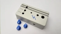
The spacing between the knobs is 17mm so you will need to order knobs which are smaller than that, I got three 16mm mini blue pointer knobs.
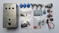
Musikding provide a Bill of Material for the kit on their website. The main build document is provided by TH Custom Effects as they designed this PCB. The schematic and additional details can also be found on runoffgroove.com.
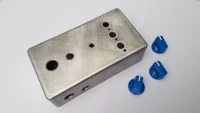
Preparing the Enclosure
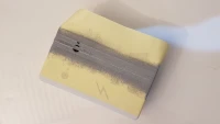
The potentiometers have a tab protruding from their base, to prevent the base from spinning when they're in use, however there were no matching slots in the enclosure. The instructions suggest snapping the tabs off with pliers as they probably aren't needed if the nut is tightened sufficiently. However, I prefer to fit things right so I drilled an additional small hole for the tab beside each existing hole. These smaller holes are not visible when the knobs are installed.
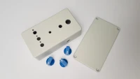
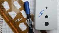
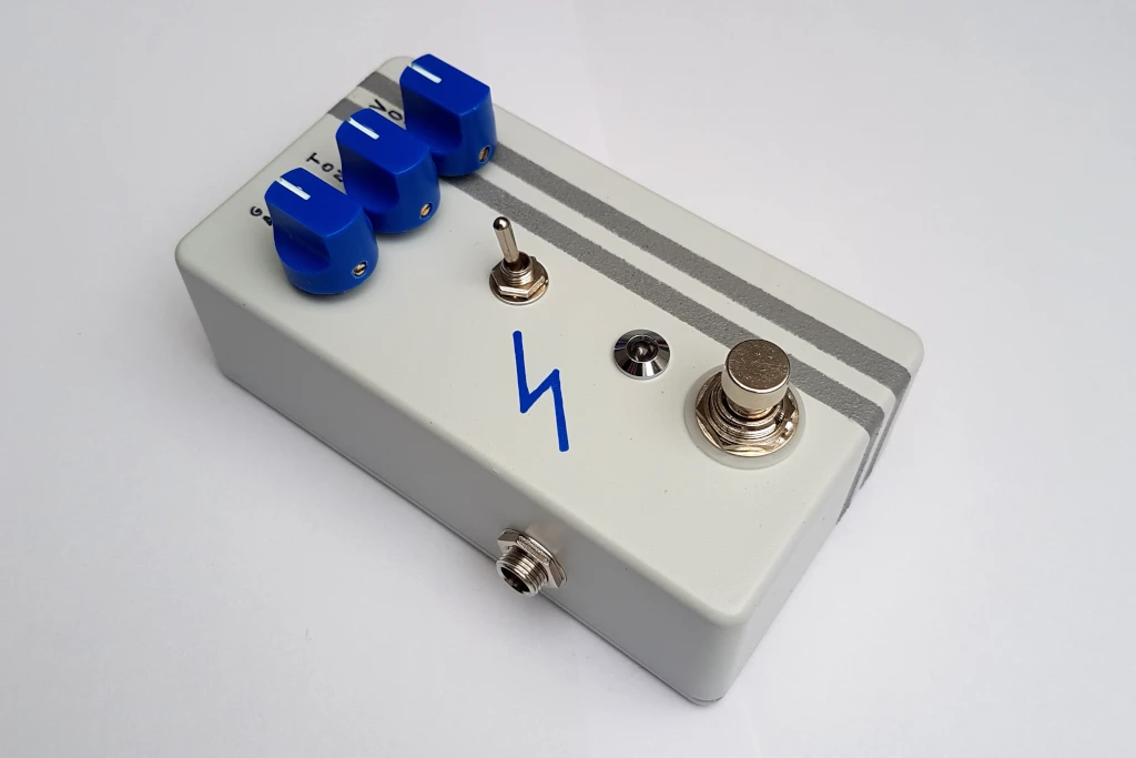
The enclosure was sprayed with several coats of light grey paint. After stenciling on some details with acrylic paint it was finished off with a few coats of matt clear-coat spray.
Assembling the PCB
This PCB is quite compact and some of the components are a tight fit, but everything is clearly labelled so it's mostly a typical assembly, going from lowest to highest parts; resistors & diodes to capacitors etc.
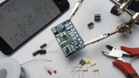
This circuit has three transistors and the kit includes three transistor sockets. However, one of the transistors, the J201 (at Q2 on the PCB), comes as a surface mounted transistor on an adapter board. The kit also includes three right-angled pins for mounting the adapter board, which is fine, however these pins do not fit into the transistor socket, they only fit directly into the main PCB. Thankfully I noticed this before soldering in the socket for the J201.
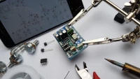
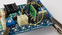
The adapter board is labelled with DSG, (Drain, Source, Gate) however the main PCB only has the standard transistor symbol, a circle with a flat side. So you need to know how the DSG pinout maps to this symbol. You can easily find this by searching for J201 pinout but it's not obvious from the build documents. You can see the J201 installed here:
Assembling the Pedal
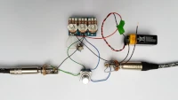
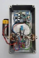
I completed and tested most of the off-board wiring before mounting in the enclosure. Thankfully everything worked when I plugged it in. When completing the assembly in the enclosure, I used a white LED instead of the red one that came with the kit and also used a higher value resistor to reduce the brightness.
In general, the build was straight forward, however there were some things that might catch you out if you're new to building pedals.
Assembly Notes
As mentioned above, the J201 transistor is surface mounted on an adapter board so you need to take care and mount this transistor correctly.
This PCB includes the "bass-boost mod" which is a nice addition, and the kit also included a switch for this mod. As this is an optional feature, there is no hole in the enclosure for the switch so you have to drill it out yourself. No big deal but it's best to do this before you paint and start assembling the components into the enclosure. The instructions don't actually describe how to connect the switch, you can work is out by comparing the schematic to the PCB; connect the switch across the two points labeled "B_B_2" and the bottom right of the PCB, simple enough but it's not obvious in the build documents.
The steps to bias the transistors are described in the build documents, and the three test points are labelled on the PCB, however you do need a multimeter for this step.
Instructions for the off-board wiring (foot-switch, LED, power and jacks) are not included in the build documents, this is not difficult if you've done it before, but it would be confusing for a beginner.
The End Result
This is a great pedal for creating some retro tones, the sample below demonstrates the dynamics on offer, it's nice and sweet when played easy but once you dig in, you can get some knarley tones.
A short demo of the pedal in action: